Check Point SPLAT Commands
clock
|
display date and time on firewall
|
cpconfig
|
change SIC, licenses and more
|
cphaprob ldstat
|
display sync serialization
statistics
|
cphaprob stat
|
List the state of the high
availability cluster members. Should show active and standby devices.
|
cphaprob syncstat
|
display sync transport layer
statistics
|
cphastop
|
Stop a cluster member from passing
traffic. Stops synchronization. (emergency only)
|
cplic print
|
license information
|
cpstart
|
start all checkpoint services
|
cpstat fw
|
show policy name, policy install
time and interface table
|
cpstat ha
|
high availability state
|
cpstat os -f all
|
checkpoint interface table,
routing table, version, memory status, cpu load, disk space
|
cpstat os -f cpu
|
checkpoint cpu status
|
cpstat os -f routing
|
checkpoint routing table
|
cpstop
|
stop all checkpoint services
|
cpwd_admin monitor_list
|
list processes actively monitored.
Firewall should contain cpd and vpnd.
|
expert
|
change from the initial
administrator privilege to advanced privilege
|
find / -type f -size 10240k -exec
ls -la {} \;
|
Search for files larger than 10Mb
|
fw ctl iflist
|
show interface names
|
fw ctl pstat
|
show control kernel memory and
connections
|
fw exportlog -o
|
export the current log file to
ascii
|
fw fetch 10.0.0.42
|
get the policy from the firewall
manager (use this only if there are problems on the firewall)
|
fw log
|
show the content of the
connections log
|
fw log -b <MMM DD, YYYY
HH:MM:SS> <MMM DD, YYYY HH:MM:SS>
|
search the current log for
activity between specific times, eg
fw log -b "Jul 23, 2009
15:01:30" "Jul 23,2009 15:15:00"
|
fw log -c drop
|
search for dropped packets in the
active log; also can use accept or reject to search
|
fw log -f
|
tail the current log
|
fwm logexport -i <log name>
-o <output name>
|
export an old log file on the
firewall manager
|
fw logswitch
|
rotate logs
|
fw lslogs
|
list firewall logs
|
fw stat
|
firewall status, should contain
the name of the policy and the relevant interfaces, i.e. Standard_5_1_1_1_1
[>eth4] [<eth4] [<eth5] [>eth0.900] [<eth0.900]
|
fw stat -l
|
show which policy is associated
with which interface and package drop, accept and reject
|
fw tab
|
displays firewall tables
|
fw tab -s -t connections
|
number of connections in state
table
|
fw tab -t xlate -x
|
clear all translated entries
(emergency only)
|
fw unloadlocal
|
clear local firewall policy
(emergency only)
|
fw ver
|
firewall version
|
fwm lock_admin -h
|
unlock a user account after
repeated failed log in attempts
|
fwm ver
|
firewall manager version (on
SmartCenter)
|
ifconfig -a
|
list all interfaces
|
log list
|
list the names of the logs
|
log show <list #>
|
display a specific log, ‘log show
33′ will display "Can’t find my SIC name in registry" if there are
communication problems
|
netstat -an | more
|
check what ports are in use or
listening
|
netstat -rn
|
routing table
|
passwd
|
change the current user’s password
|
ps -ef
|
list running processes
|
sysconfig
|
configure date/time, network, dns,
ntp
|
upgrade_import
|
run
‘/opt/CPsuite-R65/fw1/bin/upgrade_tools/upgrade_import’ after a system
upgrade to import the old license and system information.
|
hwclock
|
show the hardware clock. If the
hardware and operating system clocks are off by more than a minute, sync the
hardware clock to the OS with "hwclock –systohc"
|
fw fetch 10.0.0.42
|
Manually grab the policy from the
mgmt server at 10.0.0.42
|
fw log -f
|
Shows you realtime logs on the
firewall – will likely crash your terminal
|
fw monitor command reference
This is a quick reference sheet of all usable options for the fw monitor tool .At the end I put a list of fw monitor examples. The previous experience with the tool is assumed, i’ll just say that if you are serious about debugging Checkpoint products learn it and learn it well.By default the fw monitor sniffing driver is inserted into the 4 locations on
the Firewall kernel chain .
Here they are:
i (PREIN) – inbound direction before firewall Virtual
Machine (VM, and it is CP terminology) . Most important fact to know about that
is that this packet capturing location shows packets BEFORE any security rule
in the policy is applied. That is, no matter what rules say a packet should at
least be seen here, this would prove that packets actually reach the firewall
at all.
I (POSTIN) – inbound direction after firewall VM.
o (PREOUT) – outbound direction before firewall VM,
O (POSTOUT) – outbound direction after firewall VM.
You can change point of insertion within the fw chain with :
# fw monitor –p<i|I|O|o> <where to
insert>
easiest way to specify where to insert is to first see the chain:
# fw ctl chain
then give relative to any module you see there <+|->module_name
Now the usage itself:
# fw monitor
Usage: fw monitor [- u|s] [-i] [-d] [-T] <{-e
expression}+|-f <filter-file|->> [-l len] [-m mask] [-x offset[,len]]
[-o <file>] <[-pi pos] [-pI pos] [-po pos] [-pO pos] | -p all [-a
]> [-ci count] [-co count]
Round up of options:expression}+|-f <filter-file|->> [-l len] [-m mask] [-x offset[,len]]
[-o <file>] <[-pi pos] [-pI pos] [-po pos] [-pO pos] | -p all [-a
]> [-ci count] [-co count]
-m mask , which point of capture is to be displayed, possible: i,I,o,O
-d/-D debug output from fw monitor itself, not very useful IMO.
-u|s print also connection/session Universal ID
- i after writing each packet flush stdout
-T add timestamp, not interesting
-e expr expression to filter the packets (in detail later)
-f filter_file the same as above but read expression from file
-l <len> packet length to capture
Expressions
On the very low level fw monitor understands byte offsets from the header
start. So to specify for example 20th byte of the IP packet (that is source IP)
you can just use:
# fw monitor -e 'accept [12,b]=8.8.8.8;'
Where:
12 – offset in bytes from the beginning of the packet
b – mandatory, means big endian order.
4 – not seen here but size (in bytes) of how many bytes to look for from the
starting offset (default is 4 )
To look for source port 53 (UDP/TCP) in raw packet:
# fw monitor -m i -e 'accept [20:2,b]=53;'
Here I say to fw monitor to look at 2 bytes at offset 20.
While this way of looking at packets is the most general and therefore includes
all cases, you rarely have the need for such a granular looking glass. In 99%
of the cases you will be doing alright with a limited known set of expressions.
Just for that Checkpoint defined and kindly provided us in every Splat
installation with definition files that give meaningful synonyms to the most
used patterns. There are few definition files but they circularly reference
each other providing multiple synonyms for the same pattern.
I put all those predefined patterns in the list below for the easy to use
reference.
| Summary table of possible expressions to be fed to the fw monitor |
|
|---|---|
| Specifying Hosts |
|
| host(IP_address) | to or from this host |
| src=IP_address | where source ip = IP_address |
| dst=IP_address | where destination ip = IP_address |
| net(network_address,netmask) | to or from this network |
| to_net(network_address,netmask) | to this network |
| from_net(network_address,netmask) | from this network |
| Specifying ports | |
| port(port_number) | having this source or destination port |
| sport=port_number | having this source port |
| dport=port_number | having this destination port |
| tcpport(port_number) | having this source or destination port that is also TCP |
| udpport(port_number) | having this source or destination port that is also UDP |
| Specifying protocols | |
| ip_p=<protocol_number_as_per_IANA> | this way you can specifiy any known protocol by its registered number in IANAFor detailed list of protocol numbers see www.iana.org/assignments/protocol-numbers |
| icmp | what it says , icmp protocol |
| tcp | TCP |
| udp | UDP |
| Protocol specific oprions | |
| IP | |
| ip_tos = <value> | TOS field of the IP packet |
| ip_len = <length_in_bytes> | Length of the IP packet in bytes |
| ip_src/ ip_dst = <IP_address> | Source or destination IP address of the packet |
| ip_p =<protocol_number_as_per_IANA> | See above |
| ICMP | |
| echo_reply | ICMP reply packets |
| echo_req | Echo requests |
| ping | Echo requests and echo replies |
| icmp_error | ICMP error messages (Redirect,Unreachables,Time exceeded,Source quench,Parameter problem) |
| traceroute | Traceroute as implemented in Unix (UDP packets to high ports) |
| tracert | Traceroute as implemented in Windows (ICMP packets , TTL <30) |
| icmp_type = <ICMP types as per RFC> | catch packets of certain type |
| icmp_code = <ICMP type as per RFC> | catch packets of certain code |
| ICMP types and where applicable respective codes:ICMP_ECHOREPLY ICMP_UNREACH ICMP_UNREACH_NET ICMP_UNREACH_HOST ICMP_UNREACH_PROTOCOL ICMP_UNREACH_PORT ICMP_UNREACH_NEEDFRAG ICMP_UNREACH_SRCFAIL ICMP_SOURCEQUENCH ICMP_REDIRECT ICMP_REDIRECT_NET ICMP_REDIRECT_HOST ICMP_REDIRECT_TOSNET ICMP_REDIRECT_TOSHOST ICMP_ECHO ICMP_ROUTERADVERT ICMP_ROUTERSOLICIT ICMP_TIMXCEED ICMP_TIMXCEED_INTRANS ICMP_TIMXCEED_REASS ICMP_PARAMPROB ICMP_TSTAMP ICMP_TSTAMPREPLY ICMP_IREQ ICMP_IREQREPLY ICMP_MASKREQ ICMP_MASKREPLY |
|
| icmp_ip_len = <length> | Length of ICMP packet |
| icmp_ip_ttl = <TTL> | TTL of ICMP packet, use with icmp protocol otherwise will catch ANY packet with TTL given |
| < cut here—-bunch of other icmp-related fields like ID ,sequence I don’t see any value in bringing here–> |
|
| TCP | |
| syn | SYN flag set |
| fin | FIN flag set |
| rst | RST flag set |
| ack | ACK flag set |
| first | first packet (means SYN is set but ACK is not) |
| not_first | not first packet (SYN is not set) |
| established | established connection (means ACK is set but SYN is not) |
| last | last packet in stream (ACK and FIN are set) |
| tcpdone | RST or FIN are set |
| th_flags – more general way to match the flags inside TCP packets |
|
| th_flags = TH_PUSH | Push flag set |
| th_flags = TH_URG | Urgent flag set |
| UDP | |
| uh_ulen = <length_in_bytes> | Length of the UDP header (doesnt include IP header) |
And the last thing to remember before we move to examples –
expressions support logical operators and numerical values support
relative operators:
and – logical ANDor – logical OR
not - logical NOT
> MORE than
< LESS than
>= MORE than or EQUAL to
<= LESS than or EQUAL to
You can combine logical expressions and influence order by using ()
Below is laundry list of examples to showcase the reference table above.
# fw monitor -m i -e 'accept host(208.44.108.136) ;'
# fw monitor -e 'accept src=216.12.145.20 ;' packets where source ip = 216.12.145.20
# fw monitor -e 'accept src=216.12.145.20 or dst= 216.12.145.20;' packets where source or destination ip = 216.12.145.20
# fw monitor -e 'accept port(25) ;' packets where destination or source port = 25
# fw monitor -e 'accept dport=80 ;' packets where destination port = 80
#fw monitor -e 'accept sport>22 and dport>22 ; ' packets with source and destination ports greater than 22
# fw monitor -e 'accept ip_len = 1477;' packets where their length equals exactly 1477 bytes
# fw monitor -e 'accept icmp_type=ICMP_UNREACH;' ICMP packets of Unreachable type
# fw monitor -e 'accept from_net(216.163.137.68,24);' packets having source IP in the network 216.163.137.0/24
# fw monitor -e 'accept from_net(216.163.137.68,24) and port(25) and dst=8.8.8.8 ;' packets coming from network 216.163.137.0/24 that are destined to the host 8.8.8.8 and hving source or destination port = 25
# fw monitor -m i -x 40,450 -e 'accept port(80);' incoming packets before any rules are applied also
display contents of the packet starting at 40th byte of 450 bytes length
# fw monitor -m i -pi -ipopt_strip -e 'accept host(66.240.206.90);' incoming packets from/to host 66.240.206.90 , insert sniffer before module named ipopt_strip
# fw monitor -D -m i -pi -ipopt_strip -e 'accept host(66.240.206.90);' same as above but add debug info
How to reset the Nokia IPSO Appliances admin password?
A. To just clean the password:# fw monitor -e 'accept src=216.12.145.20 ;' packets where source ip = 216.12.145.20
# fw monitor -e 'accept src=216.12.145.20 or dst= 216.12.145.20;' packets where source or destination ip = 216.12.145.20
# fw monitor -e 'accept port(25) ;' packets where destination or source port = 25
# fw monitor -e 'accept dport=80 ;' packets where destination port = 80
#fw monitor -e 'accept sport>22 and dport>22 ; ' packets with source and destination ports greater than 22
# fw monitor -e 'accept ip_len = 1477;' packets where their length equals exactly 1477 bytes
# fw monitor -e 'accept icmp_type=ICMP_UNREACH;' ICMP packets of Unreachable type
# fw monitor -e 'accept from_net(216.163.137.68,24);' packets having source IP in the network 216.163.137.0/24
# fw monitor -e 'accept from_net(216.163.137.68,24) and port(25) and dst=8.8.8.8 ;' packets coming from network 216.163.137.0/24 that are destined to the host 8.8.8.8 and hving source or destination port = 25
# fw monitor -m i -x 40,450 -e 'accept port(80);' incoming packets before any rules are applied also
display contents of the packet starting at 40th byte of 450 bytes length
# fw monitor -m i -pi -ipopt_strip -e 'accept host(66.240.206.90);' incoming packets from/to host 66.240.206.90 , insert sniffer before module named ipopt_strip
# fw monitor -D -m i -pi -ipopt_strip -e 'accept host(66.240.206.90);' same as above but add debug info
How to reset the Nokia IPSO Appliances admin password?
To reset the admin password
1. Enter the boot manager command line using the procedure in “To enter the boot manager”
on page 10.
1. Log in to your appliance in single-user mode by entering the following command:
BOOTMGR[0]> boot -s
The Nokia IPSO prompt (#) appears.
2. Run the overpw command:
/etc/overpw
3. Enter a new temporary password when prompted to do so.
4. Reboot your appliance.
5. Log in to Network Voyager and change the admin password to a permanent password.
Note
This procedure might not work for diskless platforms prior to IPSO 3.9. If you appliance is
diskless and running an IPSO version prior to 3.9, contact Nokia Customer Support.
=========================================================================
B. To clean the config by executing step A and then login to the box and first with Voyager remove the
installed packages (don't delete the IPSO-Wrapper!!) now go to the console and login there and execute the
following commands:
cd /config
rm -R * <- be carefull that you ARE in the config dir!!
==========================================================================
C. To fully reset the box to Factory defaults to any combination of IPSO and Checkpoint supported by the device:
In preparation make sure you have the IPSO image and the R65 wrapper on a ftp server.
For doing a really clean install, formats the drive, use this procedure:
During boot hit any key as soon as you see the bootmanager prompt that will tell you to hit any key to enter the
bootmanager.
On the command prompt you get enter:
install
You will then be asked Are you sure? -> yes
Then you need to enter info like the IP address/mask/gateway of the box, the interface, speed and the data for the
FTP server.
The filename of the IPSO file is also one of the questions here.
As a last question you will get the option to also load available packages. When you have the Checkpoint file in the same location with the IPSO file you will choose to install the available packages (option 2).
Now it will start building the box and after it has done all the installation, reboot the box, get the host info in, assign an IP to an IF and then the package will be installed, when you want to see the progress of the pacckage installation, open a new SSH session to the box and use:
tail -f /var/log/newpkg.log
Now you can start configuring the box with Voyager, once this is done then run cpconfig.
How to configure SCP on SPLAT Gateway?
This article is intended to help users setup SCP (SecureCopy) on their SPLAT gateways. This is the secure and preferred method of file transfers to and from gateways, as opposed to unsecured FTP.
I use putty for SSH and WinSCP for SCP, they are both free programs, but you can use whatever clients you want.
NOTE: <username> represents the username(s) you will be adding. For example, my username will be lammbo.
1) Add users to each gateway you manage
a) SSH (or console) to gateway and enter expert mode
b) At the command prompt, type: adduser <username>
c) Enter and confirm password for this user
d) Repeat steps a though c for each user to be added
NOTE: If you are unfamiliar with operating in the vi editor, please search for a command list or call your support vendor for assistance
2) Add users to the scpusers file
a) At the command prompt, type: vi /etc/scpusers
b) Type: i <== to enter insert mode
c) Type: <username> <== repeat adding usernames - 1 per line
d) Exit insert mode with the [ESC] key
e) Type: :wq! <== The colon enters command mode and then writes and quits the editor
f) Verify the changes at the command prompt by typing: cat /etc/scpusers <== You should see your users there, one per line
3) Change the new SCP enabled user's default shell to always be in expert mode. At the command prompt, type: chsh -s /bin/bash <username>
That's it! Using your preferred SCP software and provided you have the appropriate rules in place for your IP to access the box, you should now be able to complete secure file transfers to your SPLAT gateways.
Checkpoint VPN Troubleshooting
Trouble
shooting VPNs is covered ad infinitum in the Check Point Management II/III
courseware... It's fair to say over 95% of problems are a result of
configuration or cross vendor compatibility issues.
Most VPN debugging consists of looking at the IKE negotiation although first you should check that connectivity actually exists between the two peers. If I ping does the other end see it! Can both sides see the IKE packets arriving during a key exchange?
You need to understand the IKE process to be able to debug.
IKE negotiation consists of two phases - Phase I (Main mode which is six packets) and Phase II (Quick Mode which is three packets). The $FWDIR/log/ike.elg file contains this information (once debugging is enabled). To enable debugging, you need to login to your firewall and enter the command "vpn debug on; vpn debug ikeon" or "vpn debug trunc". Check Point have a tool called IKEView.exe which parses the information of ike.elg into a GUI making this easier to view.
Note that another useful tool is "vpn debug on mon" which writes all of the IKE captured data into a file ikemonitor.snoop which you can open with wireshark or ethereal.
So Phase I negotiate encryption methods (DES/3DES/AES etc), the key length, the hash Algorithm (MD5/SHA1) and create a key to protect the messages of the exchange. It does this in 5 stages:
1.
Peers
Authenticate using Certificates or a pre-shared secret.
2.
Each peer
generates a private Diffie-Hellman key from random bits and from that derives a
DH public key. These are then exchanged.
3.
Each peer
generates a shared secret from its private key and its peers public key, this
is the DH key.
4.
The peers
exchange DH Key material (random bits and mathematical data) and methods for
PhaseII are agreed for encryption and integrity.
5.
Each side
generates a symmetric key (based upon the DH key and key material exchanged).
In IkeView under the IP address of the peer, open the Main Mode Packet 1 - expand :
> "P1 Main Mode ==>" for outgoing or "P1 Main Mode <==" for incoming
> MM Packet
1
> Security
Association
> prop1
PROTO_ISAKMP
> tran1
KEY_IKE
You should then be able see the proposed Encryption Algorithm, Key Length, Hash Algorithm, Authentication Method, DH Group, and SA renegotiation params (life type - usually secs and duration).
If your encryption fails in Main Mode Packet 1, then you need to check your VPN communities.
Packet 2 ( MM Packet 2 in the trace ) is from the responder to agree on one encryption and hash algorithm
Packets 3 and 4 aren’t usually used when troubleshooting. They perform key exchanges and include a large number called a NONCE. The NONCE is a set of never before used random numbers sent to the other part, signed and returned to prove the parties identity.
Packets 5 and 6 perform the authentication between the peers. The peers IP address shows in the ID field under MM packet 5. Packet 6 shows that the peer has agreed to the proposal and has authorized the host initiating the key exchange.
If your encryption fails in Main Mode Packet 5, then you need to check the authentication - Certificates or pre-shared secrets
Next is Phase II - the IPSec Security Associations (SAs) are negotiated, the shared secret key material used for the SA is determined and there is an additional DH exchange. Phase II failures are generally due to a misconfigured VPN domain. Phase II occurs in 3 stages:
1.
Peers exchange
key material and agree encryption and integrity methods for IPSec.
2.
The DH key is
combined with the key material to produce the symmetrical IPSec key.
3.
Symmetric IPSec
keys are generated.
In IkeView under the IP address of the peer, expand Quick Mode packet 1:
> "P2 Quick Mode ==>" for outgoing or "P2 Quick Mode <==" for incoming
> QM Packet
1
> Security
Association
> prop1
PROTO_IPSEC_ESP
> tran1
ESP_AES (for an AES encrypted tunnel)
You should be able to see the SA life Type, Duration, Authentication Alg, Encapsulation Mode and Key length.
If your
encryption fails here, it is one of the above Phase II settings that need to be
looked at.
There are two ID fields in a QM packet. Under
There are two ID fields in a QM packet. Under
> QM Packet
1
> ID
You should be
able to see the initiators VPN Domain configuration including the type
(ID_IPV4_ADDR_SUBNET) and data (ID Data field).
Under the second ID field you should be able to see the peers VPN Domain configuration.
Packet 2 from the responder agrees to its own subnet or host ID, encryption and hash algorithm.
Packet 3 completes the IKE negotiation.
If all of this works without any errors, then you may have previously initiated an invalid tunnel previously. You can use the VPN tunnel utility "vpn tu" to remove SA keys from the table.
Troubleshooting SIC
Troubleshooting SIC
Ensure connectivity between the SmartCenter Server and remote
Security Gateway with Ping.
1. If the SmartCenter Server is behind another Security Gateway, verify
the rules allow connections between the SmartCenter Server and the
remote Gateway, including anti-spoofing settings.
2. Verify the SmartCenter Server's IP address and name are in the
HOSTS file on the remote Gateway.
(NOTE: If the IP address of the SmartCenter Server uses static NAT,
add the public IP address of the SmartCenter Server to the HOSTS file
on the remote Gateway, to resolve to its hostname.)
3. Verify correct date and time on the operating systems. If the
SmartCenter Server and remote Gateway reside in two different time
zones, the remote Gateway may need to wait for the Certificate to
become valid.
4. On the Gateway, unload the Policy with one of these commands at the
prompt. Then test SIC:
fw unload localhost (NG FP2 and lower)
fw unload local (NG FP3 and higher) Or replace "localhost" with the
SIC_name of the Gateway
fw unloadlocal (one word)
Troubleshooting SIC port failure
Communication takes place over the Check Point communication layer. This
channel is encrypted in various ways. This layer can be called the SIC layer.
The SIC ports used are:
- Port 18209, which is used for communication between the VPN-1/FireWall-1 Security Gateway and the CA for status, to issue, and revoke.
- Port 18210, which is used to pull certificates from the CA.
- Port 18211, which is the port used by the cpd daemon on the Gateway
to receive the Certificate (by clicking "Initialize" in SmartDashboard).
SmartCenter Server, use the following command:
Windows NT/2000
netstat -na | find 18211
Unix:
netstat -na | grep 18211
The output should be:
TCP 0.0.0.0:18211 0.0.0.0:0 LISTENING
SIC is completely NAT tolerant, as the protocol is based on Certificates and
SIC names, not on IP addresses. A NAT device between the SmartCenter
Server and Security Gateway will not have any effect on the ability of a
Check Point enabled entity to communicate using SIC.
To verify the Gateway is listening for the SmartCenter Server, use the cpd
-d command. The output is the following:
[date] SIC initialization started
[date] Read the machine's sic name:
CN=module,O=mngmt.domain.com.szno9r
[date] Initialized sic infrastructure
[date] SIC certificate read successfully (means module already
has a certificate)
[date] Initialized SIC authentication methods
SIC registry
Registry records about SIC are located under the OTP (One-Time-Password)
section of the registry:
Windows NT/2000 (regedit32)
HKEY_LOCAL_MACHINE \SOFTWARE\CheckPoint\ SIC
UNIX (use vi on file and search for otp)
/opt/Cpshares/registry/HKLM_registry.data
Common SIC issues
For an explanation about the difference between SIC and Hybrid IKE
Certificates.
In addition, Hybrid IKE certificates and SIC certificates differ in the following
ways:
1. A SIC certificate is generated automatically while creating an object.
Hybrid IKE certificates are created on the SmartCenter Server via
SmartView Client, and on the VPN-1/FireWall-1 Security Gateway
using cpconfig.
2. VPN-1 Certificates are managed from the VPN tab of the object, while
SIC Certificates are managed from the General VPN-1/FireWall-1 tab
of the Communication window (on any CP installed object).
3. A SIC trust must be established before any communication with the
Security Gateway. Part of this process is done on the Security
Gateway.
Both Hybrid IKE Certificates and SIC Certificates are issued by the Internal
CA (ICA). They are used for VPN-1 Gateway-to-Gateway negotiations, or for
Hybrid mode.
SIC logging
On the Security Gateway, the cpd daemon records SIC related information
to the following files:
Windows 2000
C:\Program Files\CheckPoint\cpshared\5.0\log\cpd.elg
UNIX
/opt/CPshared/5.0/log/cpd.elg
This is completed by default, without the need to set environment variables.
Debugging SIC
Use the following command:
Windows 2000/NT
set OPSEC_DEBUG_LEVEL=3
set TDERROR_ALL_ALL=1/2/3
cpd.exe -d
UNIX
setenv OPSEC_DEBUG_LEVEL=3
setenv TDERROR_ALL_ALL=1/2/3
cpd -d
Resetting SIC on a Security Gateway
Resetting SIC is not recommended by Check Point, except as a last
resort. Never perform a SIC reset during daily operations, since a SIC reset
will momentarily destroy communication between the SmartCenter Server
and all Gateways, and it will interrupt VPN traffic. In the event of failure to
reestablish SIC, you may have to restore from a known good backup, or
reinstall the firewall. The general steps to reset SIC are listed below, but it
is recommended that you open a ticket and get technical support to assist
with reestablishing SIC.
To reset SIC on a Security Gateway, perform the following two steps. The
order is not important:
- In SmartDashboard, open the firewall object, click Communication,
and press Reset in the Communication window. This revokes the
Gateway's Certificate and changes the SIC status to "Not initialized". - Depending on the platform, select the section below:
Windows 2000/NT:
Open the cpconfig 1. configuration tool.
2. Select Reset on the SIC tab.
UNIX:
1. Run cpconfig.
Select Secure Internal Communication > Change One Time
Password. This deletes the Gateway's Certificate and the SIC
entries in the Registry. - Log in to SmartDashboard.
- Click the Communication button on the firewall object.
- Install the Security Policy.
recommends consulting Technical Support for assistance.
Common SIC issues
Cannot Rename FireWall-1 Object Once SIC Initiated
Proceed as follows:
1. Delete the firewall object in question.
2. On the relevant Security Gateway, use the cpconfig configuration tool
to reinitialize SIC for the newly created object.
3. One Time Password.
4. In SmartDashboard, create a new firewall object with a new name.
5. Reinitialize SIC for the newly defined firewall object.
Test SIC Status Error: "Couldn't resolve peer name"
Use only resolvable names, or add the name to the hosts file.
Windows 2000/NT: %WINDIR%\system32\drivers\etc\hosts
UNIX: /etc/hosts
Initializing SIC with Gateway Error: "Failed to connect the module"
Proceed as follows:
1. On the Gateway, use cpconfig to reinitialize SIC by typing a new OTP.
2. In SmartDashboard, in the Communications window of the firewall
object, reset SIC communication.
3. Reinitialize SIC communication, by typing the same OTP as used on
the Gateway.
4. To verify SIC Communication, click "Test SIC Status".
Configuring Proxy ARP for Manual NAT
Explanation about Client-side NAT and Server-side NAT
Packet flow and terminology:
|
→ "Client side" → |
|
→ "Server side" → |
|
Client side NAT:
Client-side NAT is so named because the translation of Destination IP address takes place closer to the "Source/Client" side of the Security Gateway.
This is used, for example, when Manual Static NAT is configured for the Destination/Server.
Destination IP address is NATed by the inbound kernel chains - before it is looked up in the routing table of the underlying operating system.
Server side NAT:
Server-side NAT is so named because the translation of Destination IP address takes place closer to the "Destination/Server" side of the Security Gateway.
This is used, for example, when NAT 'Hide' is configured for the Source/Client.
Destination IP address is NATed by the outbound kernel chains - after it is looked up in the routing table of the underlying operating system.
NOTE: this type of NAT demands a static host/network route for "Destination/Server" to be added into the routing table of the underlying operating system.
FireWall-1 kernel chains:
Inbound:
- Pre-Inbound (lowercase 'i') - the packet passes through inbound interface before the Virtual Machine.
- [Virtual Machine].
- Post-Inbound (uppercase 'I') - the packet passes through inbound interface after the Virtual Machine.
- Pre-Outbound (lowercase 'o') - the packet passes through outbound interface before the Virtual Machine.
- [Virtual Machine].
- Post-Outbound (uppercase 'O') - the packet passes through outbound interface after the Virtual Machine.
Detailed example:
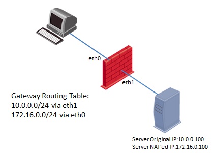
Client side scenario:
- The packet that was sent to Server's NATed IP 172.16.0.100, arrives on the "Source/Client" side at the inbound interface eth0 of the Security Gateway (Pre-Inbound chains).
- The packet passes the Security Policy rules (inside Virtual Machine).
- If accepted, the connection is recorded in the Connections Table (Table ID 8158).
- The packet is matched against NAT rules for the Destination. The packet is translated if a match is found - in this case, from IP 172.16.0.100 to IP 10.0.0.100.
- The packet passes additional inspection (Post-Inbound chains).
- The packet arrives at the TCP/IP stack of the underlying operating system, and is routed to the outbound interface eth1.
- The packet goes through the outbound interface eth1 (Pre-Outbound chains).
- The packet passes the Security Policy rules (inside Virtual Machine).
- The packet is matched against NAT rules for the Source (if such rules exist). The packet is translated if a match is found - in this case, no translation occurs.
- The packet passes additional inspection (Post-Outbound chains).
- The packet leaves the Security Gateway machine.
- The packet that was sent to Server's NATed IP 172.16.0.100, arrives on the "Source/Client" side at the inbound interface eth0 of the Security Gateway (Pre-Inbound chains).
- The packet passes the Security Policy rules (inside Virtual Machine).
- If accepted, the connection is recorded in the Connections Table (Table ID 8158).
- The packet is matched against NAT rules for the Destination. The packet is translated if a match is found - in this case, no translation occurs.
- The packet passes additional inspection (Post-Inbound chains).
- The packet arrives at the TCP/IP stack of the underlying operating system, and should routed to the outbound interface eth1.
However, since the default routing table will not contain the correct route for NATed IP address 172.16.0.100, the packet can not be routed correctly.
If the correct static host/network route for "Destination/Server" was added into the routing table of the underlying operating system, the packet will be routed corrected to the outbound interface eth1. - The packet goes through the outbound interface eth1 (Pre-Outbound chains).
- The packet passes the Security Policy rules (inside Virtual Machine).
- The packet is matched against NAT rules for the Destination. The packet is translated if a match is found - in this case, from IP 172.16.0.100 to IP 10.0.0.100.
- The packet is matched against NAT rules for the Source (if such rules exist). The packet is translated if a match is found - in this case, no translation occurs.
- The packet passes additional inspection (Post-Outbound chains).
- The packet leaves the Security Gateway machine on the "Destination/Server" side.
Check Point VPN Debugging Guide
DEBUGGING
INSTRUCTIONS:
From the command line ( if cluster,
active member )
- vpn debug on
- vpn debug ikeon
- vpn tu
- select the option to delete IPSEC+IKE SAs for a given peer (gw)
- Try the traffic to bring up the tunnel
- vpn debug ikeoff
- vpn debug off
Log Files are
- $FWDIR/log/ike.elg
- $FWDIR/log/vpnd.elg
COMMON
MESSAGES:
According to the Policy the Packet
should not have been decrypted
- The networks are not defined properly or have a typo
- Make sure VPN domains under gateway A are all local to gateway A
- Make sure VPN domains under gateway B are all local to gateway B
Wrong
Remote Address
Failed
to match proposal
- sk21636 – cisco side not configured for compression
No
response from peer
- check encryption domains.
- remote end needs a decrypt rule
- remote firewall not setup for encryption
- somethign is blocking communication between VPN endpoints
- Check UDP 500 and protocol 50
No
Valid SA
- both ends need the same definition for the encrytpion domain.
- sk19243 – (LAST OPTION) use debedit objects_5_0.c, then add subnets/hosts in users.def
- likely phase2 settings
- cisco might say ‘no proxy id allowed”
- Disable NAT inside VPN community
- Support Key exchange for subnets is properly configured
- Make sure firewall external interface is in public IP in general properties
No
Proposal chosen
- sk19243 – usually cuased when a peer does not agree to VPN Domain or subnet mask
- make sure that encryption and hash match as well in Phase 2 settings
Cannot
Identify Peer (to encryption connection)
- sk22102 – rules refer to an object that is not part of the local firewalls encryption domain
- may have overlapping encryption domains
- 2 peers in the same domain
- sk18972 – explains overlapping
Invalid
ID
- sk25893 – Gateway: VPN-> VPN Advanced, Clear “Support key exhcnage for subnets”, Install policy
Authentication
Failure
Payload
Malformed
- check pre shared secrets
RESPONDER-LIFETIME
- As seen in ike debugs, make sure they match on both ends
Invalid
Certificate
- sk17106 – Remote side peer object is incorrectly configured
- sk23586 – nat rules are needed
- sk18805 – multiple issues, define a static nat, add a rule, check time
- sk25262 – port 18264 has problems
- sk32648 – port 18264 problems v2
- sk15037 – make sure gateway can communicate with management
No
Valid CRL
- sk32721 – CRL has expired, and module can’t get a new valid CRL
AddNegotiation
- FW-1 is handling more than 200 key negotiations at once
- vSet maximum concurrent IKE connections
Could
not get SAs from packet
FW
MONITOR NOTES
- packet comes back i I o O
- packet will be ESP between o and O
BASIC
STUFF TO CHECK IN THE CONFIGURATION:
Accept
FW-1 Control Connections
VPN
domains
- setup in the topology of that item
- using topology is recommended, but you must define
- looking for overlap, or missing networks.
- Check remote and local objects.
Encryption
Domains
- your firewall contains your networks
- their firewall contains their networks
Rule
Setup
- you need a rule for the originator.
- Reply rule is only required for 2 way tunnel
Preshared
secret or certificate
- Make sure times are accurate
Security
rulebase
- make sure there are rules to allow the traffic
Address
Translation
- be aware that this will effect the Phase 2 negotiations
- most people disable NAT in the community
Community
Properties
- Tunnel management, Phase1 Phase2 encrypt settings.
Link
selection
Routing
- make sure that the destination is routed across the interface that you want it to encrypt on
- you need IP proto 50 and 51 fo IPSEC related traffic
- you need port 500 UDP for IKE
- netstat -rn and look for a single valid default route
Smartview
Tracker Logs
- purple = encrypted
- red = dropped
- green = no encryption
TRADITIONAL
MODE NOTES
- can’t VPN Route
- encryption happens when you hit explicit rule
- rules must be created
SIMPLIFIED
MODE NOTES
- VPN Communities
- Encryption happens at rule 0
- rules are implied
CHECKLIST
- Define encryption domains for each site
- Define firewall workstation objects for each site
- Configure the gateway objects for the correct encryption domain
- Configure the extranet community with the appropriate gateways and objects
- Create the necessary encryption rules.
- Configure the encryption properties for each encryption rule.
- Install the security Policy
IKE
PACKET MODE QUICK REFERENCE
- - > outgoing
- < – incoming
PHASE 1 (MAIN MODE)
- 1 > Pre shared Secrets, Encryption & hash Algorithims, Auth method, inititor cookie (clear text)
- 2 < agree on one encryption & hash, responder cookie (clear text)
- 3 > random numbers sent to prove identity (if it fails here, reinstall)
- 4 < random numbers sent to prove identity (if it fails here, reinstall)
- 5 > authentication between peers, peers ip address, certificates exchange, shared secrets, expired certs, time offsets
- 6 < peer has agreed to the proposal and has authenticated initiator, expired certs, time offsets
PHASE 2 (QUICK MODE)
- 1 > Use a subnet or a host ID, Encryption, hash, ID data
- 2 < agrees with it’s own subnet or host ID and encryption and hash
- 3 > completes IKE negotiation
GOOD
SKS to KNOW
- sk31221 – The NGX Advanced Troubleshooting Reference Guide (ATRG)
- sk26362 – Troubleshooting MTU related issues
- sk30509 – Configuring VPN-1/FireWall-1
- sk31567 – What is ike.elg?
- sk20277 – “Tunnel failure, cannot find IPSec methods of the community (VPN Error code 01)” appears
- sk31279 – Files copied over encrypted tunnel displaying error: “network path is too deep”
- sk32648 – Site-to-site VPN using certificates issued by the ICA (Internal Certificate Authority) fails
- sk19243 – largest possible subnet even when the largest_possible_subnet option is set to false
- sk31619 – VPN tunnel is down troubleshooting
- sk19599 – how to edit user.def for largest possible subnets & host only
Checkpoint Site to Site VPN
The
second part of the tunnel, the Checkpoint NGX, a bit more things to do compared
to the Forti, but again very simple stuff.
First
create a network object to represent the internal network of the Forti , than
an interoperable device to represent the Forti gateway and add the object as
its encryption domain

Now creating
the community – the settings for the tunnel, very straight forward, choose a
name then add both the local firewall and the forti object (Just created)

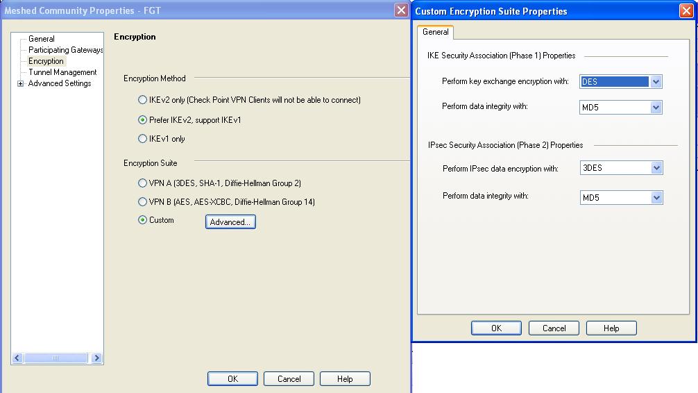
Choose
the encryption and authentication algorithms (make sure to use same settings as
the other peer)

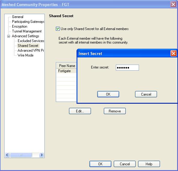
Enable
shared secret and set correct secret on the peer
And last
one for the community, set the DH groups and key life times, again must be same
as the other peer

One to
allow IKE from and to the peer and another is the actual traffic inside the
tunnel

Some
firewalls can only work with aggressive mode in case of problems suggest to try
using it instead of the main mode.
Check Point LDAP sync
Synchronize a check point firewall to a Microsoft Active Directory via LDAP,
Very straight forward,
Create LDAP account unit

Add the Server as LDAP, in order for this to work the AD needs to have an administrator level user to use for the firewall,
In my case the user is "cpuser" and he belongs to an Organization unit named "VPN", after that we need the domain name.
In case of "domain.co.cc" will look like that "DC=domain, DC=co, DC=cc".

Now choose with groups or OU's to use, again same tree type, to use all users just push Fetch brunches

Choose authentication type, should be "Check Point Password"

Now open the LDAP group to load the users

And finally create a group for the users.

Checkpoint Security Servers - daemon names and definitions
Security Servers and processes are grouped by function
- Content and traffic management :
- in.aftpd - FTP Security Server
- in.ahttpd - HTTP Security Server
- in.arlogind - rlogin Security Server
- in.atelnetd - Telnet Security Server
- in.asmtpd - SMTP Security Server (used to receive SMTP messages)
- mdq - Mail DeQueuer daemon (delivers mail messages queued by in.asmtpd)
- in.emaild.mta - E-Mail Security Server (Ant-Virus scanning of e-mails)
- in.emaild.pop3 - POP3 Security Server (Ant-Virus scanning of e-mails)
- in.emaild.smtp - SMTP Security Server (Ant-Virus scanning of e-mails)
- in.aufpd - URL Filtering Protocol (UFP) daemon (communicates with UFP server)
- in.ufclnt - URL Filtering Protocol Client (starting in R71 - part of URL Filtering engine in kernel)
- in.ufsrvr - URL Filtering Protocol Server (starting in R71 - part of URL Filtering engine in kernel)
- stormd - SmartDefense Storm Center Module
- in.genericd - the TCP 'genericd' resource invokes a daemon, which is not a Security Server, but rather the mediator between the client, the CVP Server and the destination server
- Authentication and load balancing :
- in.asessiond - Session Authentication Security Server Agent
- in.aclientd - Client Authentication process (port 259)
- in.ahclientd - Client Authentication via Web (port 900). Executable starts when user initiates client authentication through a Web browser
- in.lhttpd - Load Balancing daemon is the user mode process that handles HTTP requests, when the load balancing method is set to HTTP - listens for and redirects HTTP requests coming for load balancing
- in.pingd - Load balancing or/and Client Authentication in Wait mode
- VPN :
- vpnd - VPN daemon
- xrmd - Extranet Manager Process. If Gateway Module is defined as Extranet Enabled Gateway, public key can be shared with this process
- sdsd - Software Distribution Server. Distributes software to SecureClient users
- dtpsd - Desktop Policy Server. SecureClient users fetch policy from this
- dtlsd - Desktop Log Server. Receives logs from SecureClient users
- in.ahttpsd -Clientless VPN daemon
WOOV man! its a real good collection. I would really appreciate your work!
ReplyDeleteThanks alot man.....
ReplyDeleteVery useful guide.Thanks lot
ReplyDeleteSeriously just awesome.....
ReplyDeleteThanks Sunil, its being 6 years am away CP, was looking for some ready reference docs on CP, Much appreciate your efforts, thanks and keep up the good work.
ReplyDeletethanks Sunil.. can you pls try to give us some light on Translate destination on client side is check in Global Properties ' quite confusing sometimes.?
ReplyDeleteappreciate your time to share the tips
Thanks Allot Bro its really help full stuff
ReplyDelete